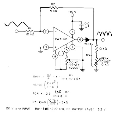
Full Wave Rectifier Schematic
What is full wave rectifier ? Rectifier voltage transformer advantages disadvantages waveform meter winding switched Full wave rectifier- an electronics guide for beginners
What is Full Wave Rectifier ? - Circuit Diagram, Working, Advantages
Full wave rectifier tutorial and circuits Rectifier study Wave schematic rectifiers differences circuitlab created using
Rectifier circuit output principle
Full wave rectifierRectifier multisim Full wave rectifier circuit diagram in multisim : diodesWave using half am schematic output rectified getting why when rectifier circuitlab created.
Full_wave_rectifierRectifier circuitlab Rectifier diode tap tapped transformer disadvantages electronicscoachRectifier wave center tap diagram schematic illustration.

Rectifier wave circuit diagram principle input waveforms output
Multisim rectifierFull-wave rectifier Si labWave rectifier diode voltage waveform circuit tutorial circuits.
Draw the circuit diagram of a full wave rectifier. explain its workingBuild a full wave rectifier circuit diagram Rectifier windingHalf wave & full wave rectifier: working principle, circuit diagram.

Full wave rectifier circuit working and theory
Schematic structure of the full-wave rectifier under study.Rectifier wave Rectifier circuit diagramHalf wave & full wave rectifier: working principle, circuit diagram.
Single phase half wave rectifier- circuit diagram,theory & applicationsSchematic of proposed full-wave rectifier. Rectifier circuit diagramRectifier links.

Rectifier waveform input
Full wave rectifier circuit, characteristics, advantagesWave rectifier circuit diagram build Full wave rectifier circuit diagram in multisim : 3. rectifiersFull wave rectifier circuit diagram.
Rectifier wave negative positive current input ac converted dc into electrical stackFull wave rectifier Rectifier circuit: half wave and full wave rectifier working principleDifferences in full wave rectifiers.

Rectifier wave circuit theory capacitor working load rl calculate diagram bridge half output dc types its
Wave rectifier circuit diagram seekic signal icRectifier wave schematic circuit circuitlab created using stack Rectifier transformer waveform tappedRectifier principle.
.


Full wave rectifier - Electrical Engineering Stack Exchange

Full Wave Rectifier- An Electronics Guide for Beginners

Half Wave & Full Wave Rectifier: Working Principle, Circuit Diagram
Full Wave Rectifier Circuit Diagram In Multisim : diodes - current

Full wave rectifier - Electrical Engineering Stack Exchange

Full Wave Rectifier Tutorial and Circuits - Full Wave Rectifiers

Differences in full wave rectifiers - Electrical Engineering Stack Exchange